Planning a new home, addition, or major renovation involves more than choosing a floor plan and deciding how the finished space should look. Before construction can begin, the design needs to be translated into a coordinated set of architectural drawings and technical documents.
A residential architectural plan set communicates how a building is positioned on its property, how its rooms are arranged, what it looks like from the outside, and how important building elements are designed. These drawings help architects, engineers, contractors, and local building departments understand the proposed work.
In California, the exact documents required depend on the project type, its complexity, applicable building codes, and the local jurisdiction reviewing the plans.
Below is an overview of the most common components of a residential architectural plan set and how they contribute to the design and permitting process.
What is a residential architectural plan set?
A residential architectural plan set is a coordinated collection of drawings, notes, dimensions, and project information describing a proposed home or residential improvement.
It translates the design concept into technical information that can be reviewed, developed, and used during construction.
Depending on the project, the set may include architectural drawings, structural plans, mechanical, electrical and plumbing information, energy compliance documentation, and other supporting materials.
For a new custom home, the documentation is generally more extensive than for a limited interior renovation. Projects involving additions, ADUs, hillside properties, or structural modifications may also require additional drawings and engineering information.
If you’re planning a new residence, our custom home design services can help you understand the architectural planning involved before moving toward construction.
1. Cover sheet and project information
The cover sheet introduces the project and provides information needed to identify and review the drawing package.
It commonly includes:
- Project name and property address.
- Property or parcel identification information.
- Project description and scope of work.
- Existing and proposed building areas.
- Applicable code and project data.
- Design team and consultant information, where applicable.
- Drawing index listing the sheets included in the set.
- General project notes and relevant code information.
This sheet gives reviewers and project participants a quick overview of the proposed work and helps them navigate the remaining drawings.
2. Site plan
The site plan shows where the existing and proposed buildings are located in relation to the property boundaries and surrounding conditions.
It is particularly important because a building must fit within the property’s applicable development requirements, not just within the available physical space.
A typical residential site plan may show:
- Property boundaries and lot dimensions.
- Existing and proposed structures.
- Building setbacks from property lines.
- Driveways, access points, and parking areas.
- Easements and relevant site restrictions.
- North arrow and street locations.
- Existing and proposed site features.
- Trees, utilities, grading, and drainage information, when required.
For hillside or sloped properties, additional topographic information, grading plans, retaining wall details, and drainage documentation may be necessary.
The site plan helps establish whether the proposed building arrangement is compatible with the property’s physical conditions and applicable zoning requirements.
3. Existing conditions and demolition plans
For a remodeling or addition project, the design team needs to understand the building as it currently exists.
Existing-condition drawings document the current layout and relevant building features. Demolition plans identify which walls, fixtures, doors, windows, or other elements are intended to be removed or modified.
These drawings help distinguish between what is already on the property and what the proposed project will change.
They may include:
- Existing floor plans and room dimensions.
- Existing exterior elevations, where relevant.
- Walls and building elements to be removed.
- Areas and components that will remain.
- Notes identifying proposed modifications.
Clear existing and demolition drawings are especially useful for projects involving changes to room layouts, structural walls, or building systems.
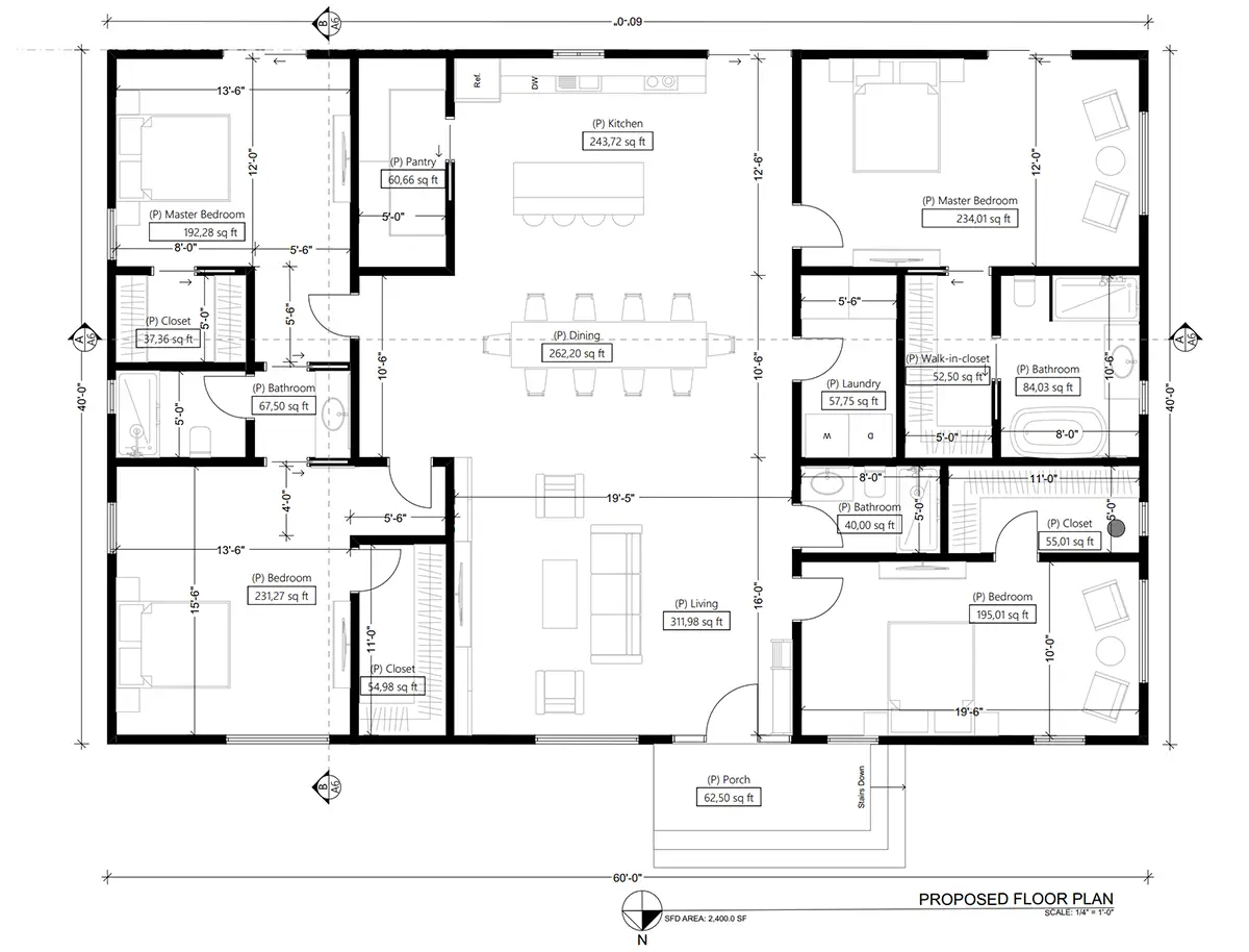
4. Floor plans
Floor plans are among the most important parts of an architectural drawing set. They show the arrangement of rooms and other spaces as viewed from above.
A complete floor plan typically identifies:
- Room names and intended uses.
- Interior and exterior wall locations.
- Overall and individual room dimensions.
- Doors, windows, and opening locations.
- Stairs and circulation paths.
- Kitchen cabinets and built-in elements.
- Bathroom fixtures and plumbing locations.
- Important equipment and appliances, where applicable.
Each level of a multi-story residence generally requires its own floor plan.
Dimensions and annotations help explain how spaces relate to one another and provide information needed for design coordination and construction.
Floor plans also make it easier to evaluate circulation, room proportions, storage, and the relationship between private and shared living areas.
5. Roof plan
The roof plan shows the configuration of the building’s roof when viewed from above.
Depending on the design, it may identify:
- Roof shape and slope direction.
- Ridges, valleys, and roof edges.
- Roof pitch and drainage direction.
- Skylights and roof openings.
- Chimneys and other penetrations.
- Roof-mounted mechanical equipment, where applicable.
- Relevant dimensions and construction notes.
The roof plan helps coordinate the architectural design with structural framing, drainage, and other building requirements.
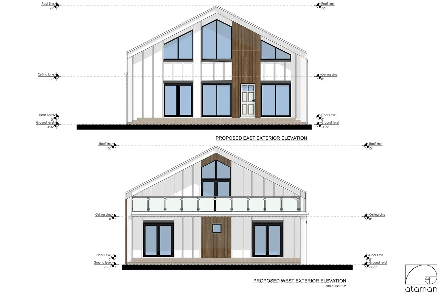
6. Exterior elevations
Exterior elevations show the building from the outside, typically from the front, rear, and both sides.
They communicate the home’s appearance, proportions, heights, and relationship to the surrounding site.
Elevations commonly include:
- Building height and exterior dimensions.
- Window and door locations.
- Rooflines and roof pitch.
- Exterior wall materials and finishes.
- Decks, balconies, stairs, and other exterior features.
- Existing and proposed ground levels, where relevant.
These drawings help reviewers understand the proposed exterior design and evaluate applicable height, setback, and other development requirements.
They are also useful for coordinating exterior materials and architectural details before construction.
7. Building sections
A building section is a vertical cut through the structure that reveals information that cannot be fully understood from a floor plan or exterior elevation alone.
Sections help explain how different levels and building elements connect.
Depending on the project, they may show:
- Floor-to-floor and ceiling heights.
- Foundation and floor relationships.
- Wall and roof assemblies.
- Stair configurations.
- Roof structure and slopes.
- Insulation and other relevant construction layers.
- Building height in relation to existing or proposed grade.
Sections are particularly useful for projects involving multiple stories, changes in floor levels, complex roof forms, or sloped properties.
8. Architectural details and schedules
Architectural details provide a closer look at specific building components that need additional explanation.
Rather than showing the entire building, these drawings focus on individual assemblies, connections, and design features.
Examples include:
- Wall sections and exterior wall assemblies.
- Window and door installation details.
- Roof edges and waterproofing transitions.
- Stairways, handrails, and guardrails.
- Deck and balcony connections.
- Exterior material transitions.
- Custom architectural features.
Schedules may also be included to organize information about windows, doors, finishes, and other specified components.
These details help clarify how design elements are intended to be constructed and coordinated.
9. Structural drawings and calculations
Structural documentation addresses how the building supports its own weight and withstands applicable loads, including seismic and wind forces.
Depending on the project, structural drawings may include:
- Foundation plans.
- Floor and roof framing plans.
- Beam and column locations.
- Shear walls and lateral bracing.
- Structural connection details.
- Retaining wall designs, where applicable.
- Structural specifications and calculations.
Structural engineering is typically prepared by a qualified structural engineer or another appropriately licensed professional, depending on the scope and applicable requirements.
The architectural and structural drawings need to work together so that the proposed design can be developed into a coordinated building system.
10. Mechanical, electrical, and plumbing plans
Mechanical, electrical, and plumbing information is often referred to as MEP documentation.
These plans describe building systems that support everyday residential use.
Mechanical plans may show heating, ventilation, and air conditioning equipment, ductwork, registers, and related components.
Electrical plans may identify lighting, switches, outlets, electrical panels, smoke alarms, and other electrical requirements.
Plumbing plans may show water supply lines, drainage, plumbing fixtures, water heaters, and related connections.
The amount of MEP documentation depends on the project. A new residence or substantial renovation may require more detailed system drawings than a project limited to cosmetic improvements.
These documents may be prepared by specialized consultants or coordinated with the architectural drawings as appropriate.
11. Energy compliance and green building documentation
California residential projects may require energy compliance documentation and other information related to applicable green building standards.
Energy-related documents can address:
- Insulation and building envelope performance.
- Window and glazing specifications.
- Heating and cooling equipment.
- Ventilation requirements.
- Lighting and other regulated building systems.
- Energy performance calculations and compliance forms.
California’s 2025 Building Energy Efficiency Standards took effect on January 1, 2026. Permit applications submitted on or after that date must comply with the applicable 2025 Energy Code requirements.
Depending on the project, the submission may also require CALGreen documentation and other supporting forms.
These requirements should be considered during design development rather than treated as paperwork to complete at the end.
12. Additional documents required for certain projects
Not every residential project requires the same technical information. Some properties and building conditions call for additional studies, drawings, or reports.
Examples include:
Grading and drainage plans
May be needed when a project changes site elevations, drainage patterns, or other relevant site conditions.
Topographic and boundary surveys
Help establish property dimensions, elevations, existing structures, and other physical conditions.
Geotechnical reports
May be required to evaluate soil conditions and provide information relevant to foundations, retaining walls, and site development.
Landscape plans
May be requested when the project involves landscaping, tree protection, irrigation, or applicable local development requirements.
Civil engineering documents
May address site grading, drainage, utilities, and other infrastructure-related requirements.
The need for these documents depends on the property’s characteristics, project scope, and reviewing agencies.
Is an architectural plan set the same as a permit application package?
Not necessarily.
An architectural plan set is primarily the collection of drawings and technical information describing the proposed building.
A complete permit application package may include the drawings along with additional materials, such as:
- Building permit application forms.
- Property surveys and supporting reports.
- Structural calculations.
- Energy compliance documents.
- Required planning approvals or clearances.
- Other forms and documentation requested by the local jurisdiction.
For example, the City of Berkeley identifies a cover sheet, site plan, architectural details, structural plans, MEP design, and energy and green building documentation among the materials required for its plan review process.
The exact submission requirements vary by city and project type. A drawing package that is sufficient for one jurisdiction may need additional information before another jurisdiction will accept it for review.
This distinction is important when preparing a project for permitting. Completing the architectural drawings does not automatically mean that every application requirement has been satisfied.
Who prepares the different parts of a residential plan set?
A residential plan set often involves several professionals working together.
Architects develop the architectural design and prepare or coordinate the architectural drawings within their scope of services.
Structural engineers design structural systems and prepare related drawings and calculations when required.
Mechanical, electrical, and plumbing consultants develop the technical documentation for their respective building systems when the project requires specialized design.
Civil engineers and surveyors may provide site-related information, grading, drainage, utility plans, and property measurements.
Energy consultants may prepare energy compliance calculations and supporting documentation when needed.
The project team depends on the size, complexity, and technical requirements of the proposed work. Not every project needs every consultant.
What should you prepare before starting architectural plans?
Having the right information available at the beginning can make the design process more efficient.
Before starting, consider gathering:
- Property address and parcel information.
- Existing floor plans, if available.
- A current property survey, if available or required.
- Photographs of the existing home and site.
- A description of the proposed work.
- Your priorities for room layouts, size, and functionality.
- An initial project budget.
- Any known property restrictions, easements, or previous permit records.
For an existing home, accurate information about the current building is especially valuable. Missing dimensions or undocumented modifications may need to be investigated before the drawings can be developed.
A clear understanding of the project goals also helps the design team determine which drawings, consultants, and approvals may be necessary.
Frequently asked questions
How many sheets are included in a residential architectural plan set?
There is no standard number of sheets for every residential project. A simple renovation may require a relatively small drawing package, while a new custom home or complex addition may need multiple architectural, structural, and engineering sheets.
Are architectural plans required to obtain a building permit in California?
Many construction projects, including new homes, additions, and substantial renovations, require plans for local building department review. The exact documentation depends on the scope of work and the jurisdiction. Some limited projects may have simplified requirements or exemptions.
Do architectural plans include structural engineering?
Not always. Architectural drawings describe the building design, while structural drawings and calculations address the structural system. These documents may be prepared separately by a qualified structural engineer and coordinated with the architectural set.
Do I need Title 24 documentation for a residential project?
Energy compliance documentation may be required depending on the type and scope of work. California’s applicable Energy Code requirements should be evaluated early in the design process, including the 2025 standards effective January 1, 2026.
Can I use the same architectural plan set in every California city?
Not necessarily. California has statewide building standards, but local jurisdictions may have additional submission procedures, amendments, and project-specific requirements. Plans may need to be adjusted to satisfy the reviewing authority.
Does a complete architectural plan set guarantee permit approval?
No. A complete and coordinated drawing package supports the review process, but the local authority makes the final determination. Reviewers may request clarifications, additional documents, or revisions before issuing a permit.
How long does it take to prepare residential architectural plans?
The timeline depends on project size, design complexity, existing site information, consultant coordination, and the number of design revisions. A new custom home generally requires more planning and documentation than a limited renovation. Permit review is a separate stage and can add additional time.
Start planning your residential project
A well-prepared architectural plan set gives everyone involved a clearer understanding of the proposed building, from the overall layout to the technical details that support construction.
Whether you’re considering a custom home, a residential addition, or a major renovation, understanding the documentation involved is a useful first step toward making informed decisions.
Ataman Studio Architects provides architectural design and planning services for residential projects in Los Angeles and throughout California. Explore our architectural services or custom home design to learn how we can help develop your project.